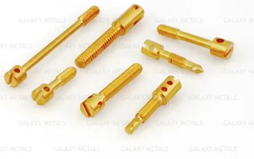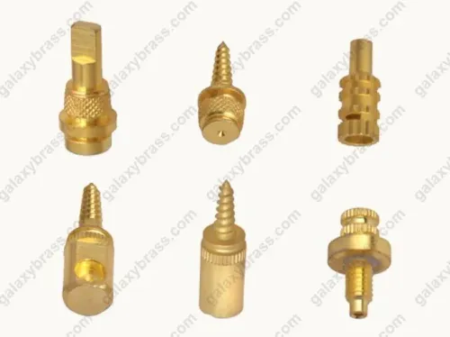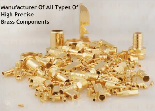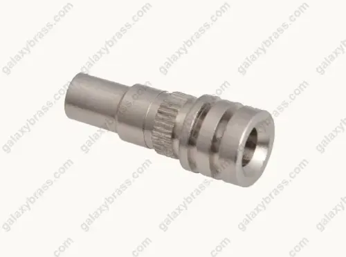
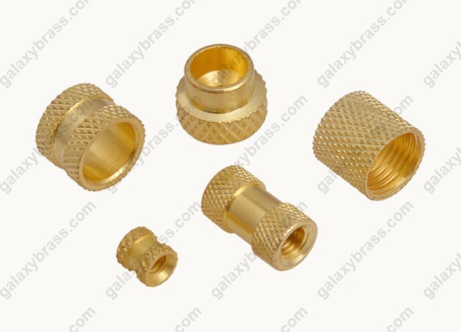
A custom moulding order does not automatically include a standard bag of brass inserts. You need to define the insert’s retention shape, thread, dimensions, material, finish, loading method and inspection requirements before a supplier can quote the correct part and the overmoulding work attached to it.
Key takeaways
- Use knurls, flats, shoulders or flanges to resist rotation and pull-out.
- Choose round, square or hexagonal inserts according to load and available mould space.
- Put thread, length, tolerance, brass grade, finish and installation method on the drawing.
- Validate fit, torque, pull-out resistance and plastic damage before production approval.
What a brass moulding insert does inside a plastic part
A brass moulding insert creates a durable threaded or locating feature inside an injection-moulded or compression-moulded plastic part. During filling, plastic flows around external knurls, flats, shoulders or flanges. After cooling, polymer shrinkage grips these features, resisting rotation and axial pull-out while the internal thread carries screw or stud loads.
The insert is not automatically included in a custom moulding order. State whether the quotation covers loose inserts, mould loading, or completed overmoulded parts. In Jamnagar quotations, specify custom brass moulding inserts as a drawing-based requirement, not a standard assortment.
Define these points before approval:
- Specify the insert’s external retention geometry, embedment length, boss wall thickness, polymer grade, moulding conditions and required assembly torque.
- Check for insert rotation, axial pull-out, plastic cracking, short shots around knurls or corners, flash in the thread, and displacement during mould closing.
- Treat brass hardness as only one material property; retention geometry, polymer shrinkage, boss design and embedment control performance.
- Require thread gauging, external dimensional checks, burr and plating inspection, then pull-out and torque tests in the actual polymer and boss geometry.
A harder brass grade cannot rescue poor geometry or insufficient plastic cover.
When round, square and hexagonal inserts provide the right retention
A round body is the safer choice when the mould cannot tolerate orientation features or the plastic must surround the insert evenly. A knurled circumference distributes grip around the boss, while flats create concentrated corner loads and demand more radial clearance.
| Shape | Main retention | Boss and mould constraints |
|---|---|---|
| Brass round knurled inserts | Circumferential grip resists rotation and axial pull-out | Compact radial clearance; smooth orientation; even plastic flow around the body |
| Brass square inserts | Four flats provide positive anti-rotation; embedment resists pull-out | Orient the insert; cover each corner with enough plastic to prevent cracking and short shots |
| Brass hexagonal inserts | Six flats provide positive anti-rotation | Requires orientation and corner cover; not automatically stronger than a square insert |
A hexagon’s result depends on across-flats size, embedment length, polymer strength and surrounding wall thickness—not the number of flats alone. Check the boss, not just the insert.
Knurl geometry changes the balance between pull-out, torque resistance and filling. Diamond knurling grips in multiple directions; straight knurling gives predictable circumferential engagement; unidirectional knurling can favour axial or rotational resistance according to its orientation.
Specify tooth form, pitch, major diameter and run-out: coarse or oversized teeth can restrict plastic flow, while poor run-out can create uneven cover and local short shots.
Which insert configuration and dimensions belong on the drawing
Select the internal feature by the mating part, then specify external retention separately. A female threaded or tapped-hole form receives a screw; a male threaded form receives a nut. Through-threaded inserts suit bolts passing completely through, while blind-threaded inserts suit a captive joint entered from one side.
| Form | Suitable use |
|---|---|
| Female threaded | Screw fastening into the moulded part |
| Male threaded | Stud, nut, or panel-mounted fastening |
| Through-threaded | Bolt passing through the insert |
| Blind-threaded | Captive screw joint from one side |
| Plain locating | Dowel, pin, or alignment feature |
| Tapped-hole | Machined internal thread for a service screw |
| Stepped | Different diameters for staged seating or retention |
| Shouldered | Positive axial location against a boss |
| Flanged | Larger seating area and pull-out resistance |
| Slotted | Orientation, anti-rotation, or installation access |
A blind insert needs usable thread depth plus bottom clearance; otherwise the screw bottoms out before clamping. State internal thread requirements independently from external diameter, flats, knurl, shoulder, or flange geometry when ordering custom brass moulding inserts.
- Internal thread: M4 × 0.7, not “M4”; tolerance class to ISO 965-1 and gauging to ISO 1502 where applicable
- External diameter or across-flats size; overall length
- Head or flange diameter and thickness; bore depth
- Lead-in chamfer and knurl height
- Locating shoulder position; concentricity between thread and retention surface
- Tolerances for every critical dimension
How to check fit, brass grade and finish before ordering
1. Test the insert in the actual plastic part, not in isolation. Seat the flange fully, install the specified mating fastener, and confirm the thread engagement length, screw clearance, insert-to-boss clearance, minimum wall thickness, and flange seating.
2. Repeat the assembly to expose trouble: a screw that bottoms out before clamping, a flange that leaves a gap, sink marks over a shoulder, or cracks at boss corners signals a geometry problem. Record the resin and the measured clearances on the drawing.
3. Name the moulding resin, operating temperature, moisture exposure, electrical requirements, and corrosion environment before selecting brass. C36000 and CuZn39Pb3/CW614N suit machining, but electrical, drinking-water, or RoHS-controlled applications can require low-lead or lead-free grades.
4. Treat lead compliance as a substrate issue, not a surface-finish claim. For EU RoHS, request material certification or test evidence for the brass; a plated insert can still exceed the 0.1% lead limit in the homogeneous substrate.
5. If plating is required, specify nickel, tin, silver, or gold; coating thickness; coverage; thread allowance; and post-plating gauging. Plating changes mating dimensions and can restrict internal thread clearance or create intermittent defects. Require a trial assembly after plating.
How installation method changes the moulding order and validation plan
Heat staking and ultrasonic insertion fit the insert after moulding; press fitting also follows moulding, while mould-in placement loads the insert before the cavity closes.
| Method | Order and process controls | Main risk |
|---|---|---|
| Heat staking | Control heat energy, force, insertion depth, tip alignment and polymer response | Softened plastic, tilt or insufficient embedment |
| Ultrasonic insertion | Control weld energy, force, depth, horn alignment and polymer response | Cracking, flash or thread damage |
| Press fitting | Specify controlled interference, lead-in chamfer and boss dimensions | Splitting, distortion or incomplete seating |
| Mould-in placement | Control loading accuracy, orientation, cavity clearance and resistance to movement during closing and filling | Displacement, short shots or flash |
Do not assign temperatures or forces without the resin grade and insert drawing. Manual loading, pick-and-place equipment and automated loading also change the required shoulder, chamfer, orientation feature and allowable dimensional variation.
For a Jamnagar quotation, Galaxy Metals can be considered for drawing-based custom brass moulding inserts, but state whether the supplier makes inserts, loads them, overmoulds the parts, provides batch traceability and handles delivery.
Validate the finished assembly with thread gauges, external measurement, burr and plating inspection, then run pull-out and torque tests in the actual polymer and boss geometry.
Frequently asked questions
What does a brass moulding insert do inside a plastic part?
It creates a durable threaded or locating feature. Plastic flows around the insert’s external knurls, flats, shoulders or flanges, then grips them after cooling.
When should you choose round, square or hexagonal brass inserts?
Choose the insert shape according to the required resistance to rotation, axial load, available mould space and the plastic part’s geometry. Round knurled inserts suit many general applications, while square and hexagonal inserts add anti-rotation flats.
Which details belong on a custom brass moulding insert drawing?
Specify the insert shape, thread size and class, outside dimensions, overall length, knurl or flat pattern, shoulder or flange geometry, tolerances, brass grade, surface finish and installation method.
How does installation method change moulding validation?
Press-in, heat-staked, ultrasonic, over-moulded and post-moulded installation impose different fit, temperature and load requirements. Validate insertion force, seating, thread function, torque and pull-out resistance for the selected method.
Keywords